Do you dream of having a healthy microclimate in your home and not a single room smelling musty and damp? In order for the house to be truly comfortable, it is necessary to carry out proper ventilation calculations even at the design stage.
If this important point is missed during the construction of a house, you will have to solve a number of problems in the future: from removing mold in the bathroom to new renovations and installing an air duct system. Agree, it’s not very pleasant to see breeding grounds for black mold in the kitchen on the window sill or in the corners of the children’s room, and to plunge into renovation work all over again.
The article we presented contains useful materials on the calculation of ventilation systems and reference tables. Formulas, visual illustrations and a real example for premises of various purposes and a certain area, demonstrated in the video, are provided.
PHYSICAL COMPONENTS OF CALCULATIONS
According to the method of operation, ventilation circuits are currently divided into:
- Exhaust. To remove used air.
- Inlet. To let in clean air.
- Recuperative. Supply and exhaust. Remove the used one and bring in a clean one.
In the modern world, ventilation schemes include various additional equipment:
- Devices for heating or cooling supplied air.
- Filters for purifying odors and impurities.
- Devices for humidification and air distribution throughout rooms.
When calculating ventilation, the following values are taken into account:
- Air consumption in cubic meters/hour.
- Pressure in air channels in atmospheres.
- Heater power in kW.
- Cross-sectional area of air channels in sq. cm.
The simplest and most inexpensive way to install ventilation
During the construction of apartment buildings, and often private ones, only natural ventilation is provided. This cannot be said that this is bad or wrong, but only if it was really provided for. The principle of operation of such air exchange is very simple. Fresh air filled with oxygen enters the apartment or house through the natural cracks of windows and doors. Passing through all the rooms, picking up odors and excess humidity, it is saturated with carbon dioxide and rushes to the ventilation grilles located in the sanitary rooms and in the kitchen.
Disadvantages of natural ventilation
This type of natural ventilation is ideal. In real life, everything is much more complicated.
- Sealed metal-plastic windows and modern door designs with seals interfere with the free flow of air.
- Good operation of natural ventilation (with supply and exhaust) is ensured only in the cold season, when there is a temperature difference between indoors and outdoors. At other times, its operation can be facilitated by supply and exhaust fans.
Calculation of exhaust ventilation example
Before starting the calculation of exhaust ventilation, it is necessary to study the SN and P (System of Norms and Rules) design of ventilation systems. According to SN and P, the amount of air required for one person depends on his activity.
Low activity – 20 cubic meters/hour. Average – 40 kb.m./hour. High – 60 kb.m./h. Next, we take into account the number of people and the volume of the room.
In addition, you need to know the frequency - a complete exchange of air within an hour. For a bedroom it is equal to one, for living rooms - 2, for kitchens, bathrooms and utility rooms - 3.
For example, calculate the exhaust ventilation of a room of 20 sq.m.
Let's say two people live in a house, then:
V (volume) of the room is equal to: SxH, where H is the height of the room (standard 2.5 meters).
V = S x H = 20 x 2.5 = 50 cubic meters.
Next V x 2 (multiplicity) = 100 kb.m./h. Otherwise – 40 kb.m./h. (average activity) x 2 (persons) = 80 cubic meters/hour. Choose a higher value – 100 kb.m./h.
In the same order, we calculate the exhaust ventilation performance of the entire house.
How to calculate fan performance
The calculation algorithm is as follows:
- Measure the exact dimensions of the room.
- Multiply the volume by the established air exchange rate.
- The result obtained is the required productivity of the ventilation unit.
Additionally, the cross-section of the air ducts, their geometric configuration, and the resistance of the filter elements are taken into account. The power calculation formula is as follows: L = n*V, where:
- L – required system productivity;
- n – air exchange standards provided for by SNiP;
- V is the total cubic capacity of the room.
The throughput of the installation is also determined by the diameter of the air channels. Constantly running fans for ventilation must be at least 100 mm.
Calculation of exhaust fan performance in residential premises
Correct calculation of the required performance of the ventilation unit will ensure proper efficiency. To do this, you need to correctly calculate the volume of air, which should be constantly updated. An important requirement for the hood is to ensure a complete exchange of the atmospheric mixture every 15 minutes. According to current regulations, in the kitchen this figure should be at least 9 times per hour.
In the bathroom 5-8 times are enough. To accurately calculate the required productivity of a climate control device, you should know the size of the room being served, which is multiplied by the set air exchange rate. For a kitchen with a volume of 20 m³, the power calculation is carried out as follows: 20x9 = 180 m³/h. This is the minimum acceptable value.
Determining the volume of the room
The cubic capacity of a room is calculated by multiplying the length, width and height. The mathematical formula is as follows: V=a*b*c. The design power of a fan for a bathroom with a volume of 22.5 m³ should be at least 270 m³, which will ensure a complete renewal of the atmospheric mixture every 5 minutes. Additionally, in this room it is necessary to take into account the need to remove water vapor and polluted air. If you perform calculations without taking into account the increased density of the exhaust atmospheric mixture, then the exhaust system may not be able to cope with the load.
For the bathroom and kitchen, it is advisable to choose a fan with a performance reserve to ensure the proper quality of the air mixture in any conditions. The design of the ventilation system also has a significant impact on performance. The corrugated walls of the air duct take approximately 7-9% of the device's power. Losses of filters and noise-absorbing elements are indicated in the accompanying technical documentation. Each right angle of the air duct takes another 2-3% of the power.
Selecting a fan based on the minimum required performance
A certain reserve is included in the design capacity of the ventilation system. In practice, a less productive installation is sufficient. An exhaust fan for a kitchen or bathroom must cope with extreme loads, which include:
- cooking food;
- oven operation;
- taking a shower associated with intense steam formation.
Therefore, the calculation of fan performance is carried out with some margin. Modern models of ventilation systems necessarily have an enhanced operating mode. To ensure the minimum norm under standard conditions, a good air flow and draft in the channel are sufficient.
Intelligent VAV systems can reduce costs and ensure proper sanitation. They have sufficient ventilation and the ability to manually adjust by turning off or limiting air exchange in individual rooms. The required fan performance should not be determined based on a simple formula that does not take into account additional factors. These include:
- The principle of operation of the unit. Modern ventilation systems can operate in standard air exchange or recirculation mode, in which the installation's performance is lower, but it requires more power.
- Placement method. The location of the device in the room also affects the ability to update the atmospheric mixture. The kitchen hood is placed directly above the stove to increase the efficiency of suction of contaminated air.
- Energy consumption. The most economical option is an axial exhaust fan.
In residential premises, a market novelty is often installed - a centrifugal-type device.
Calculation of fan performance for special industrial conditions
When calculating the required performance of a ventilation unit for complex industrial facilities, a technical specification is first drawn up, which includes the expected operating conditions of the climate system. Among them:
- position of the object on the ground;
- the purpose of each room;
- layout and layout of the structure;
- properties of building materials;
- the approximate number of people permanently present inside the building;
- specifics of production and features of technological processes.
Based on this data, calculations of the required power are performed. Additionally, the following are taken into account:
- Air flow speed.
- System noise level.
- Length, geometric configuration and diameter of ventilation ducts.
- Pressure indicators.
These factors are individual for each industrial facility. The standard air flow speed is 2.5-4 m/s.
Recording the number of people in the room
The performance of the ventilation unit is also affected by the number of people constantly present in the room. There is a special formula that takes this factor into account. It looks like this: L=N*LH.
- L – minimum required device power;
- N is the number of people constantly present at the facility;
- LH – estimated volume of atmospheric air consumption by 1 person.
The norm of the air mixture in a calm state is 30 m³/h, and during physical activity the body is twice as much. For residential buildings, the value of 60 m³/h is taken as the basis for calculating the required power of the exhaust system. In rest areas, for example, in the bedroom, the standard indicator is 30 m³/h, since during sleep and in the absence of physical activity, the human body’s oxygen consumption is significantly reduced.
The hood fan used in the kitchen must have some power reserve, since the conditions here are constantly changing. Sometimes higher performance is required, for example when frying food. In a kitchen or bakery with a volume of 30 m³, it is recommended to install a fan with a design power of 400-800 m³/h. Standard air ducts pass no more than 180 m³ within 1 hour.
Therefore, in technical premises, special powerful recirculation systems are used that drive the atmospheric mixture through filter elements. They reduce productivity. Therefore, approximately 40% is added to the design power. Thus, you should choose a recirculation system with a rated productivity in the range of 560-1120 m³/h.
Increased moisture
Equipping rooms with high humidity with an exhaust system has its own peculiarities. To eliminate the possibility of a short circuit in the event of a violation of the integrity of the electrical wiring insulation, special fans with a splash-proof design are used. This model prevents the penetration of droplets and vapors into the air duct.
Regular renewal of air in rooms with poorly established natural ventilation will prevent condensation from settling on tiled and polished surfaces and will reduce the likelihood of mold formation. Modern models of exhaust systems designed for rooms of this type are equipped with a humidity sensor. In a bathroom with an area of more than 5 m², care should be taken to effectively remove the waste air mixture. An exhaust fan with a declared capacity of at least 320 m³/h is recommended.
Calculation of exhaust ventilation for industrial premises
When calculating the exhaust ventilation of a production room, the multiplicity is 3.
Example: garage 6 x 4 x 2.5 = 60 cubic meters. 2 people work.
High activity – 60 cubic meters/hour x 2 = 120 cubic meters/hour.
V – 60 cubic meters x 3 (multiplicity) = 180 kb.m./h.
We choose a larger one - 180 cubic meters / hour.
As a rule, unified ventilation systems are divided into:
- 100 – 500 cubic meters/hour. - apartments.
- 1000 – 2000 cubic meters/hour. – for houses and estates.
- 1000 – 10000 cubic meters/hour. – for factory and industrial facilities.
Selecting the height of the pipes
The next step is to determine the traction force that occurs inside the exhaust unit at a given height difference. The parameter is called available gravitational pressure and is expressed in Pascals (Pa). Calculation formula:
- p – gravitational pressure in the channel, Pa;
- H – height difference between the outlet of the ventilation grille and the cut of the ventilation duct above the roof, m;
- ρair – room air density, take 1.2 kg/m³ at home temperature +20 °C.
The calculation method is based on selecting the required height. First, decide how much you are willing to raise the exhaust pipes above the roof without damaging the appearance of the building, then substitute the height value into the formula.
Example. We take a height difference of 4 m and get the thrust pressure p = 9.81 x 4 (1.27 - 1.2) = 2.75 Pa.
Now comes the most difficult stage - the aerodynamic calculation of the outlet channels. The task is to find out the resistance of the air duct to the flow of gases and compare the result with the available pressure (2.75 Pa). If the pressure loss is greater, the pipe will have to be expanded or the bore diameter increased.
The aerodynamic resistance of the air duct is calculated by the formula:
- Δp – total pressure loss in the shaft;
- R – specific frictional resistance of the passing flow, Pa/m;
- H – channel height, m;
- ∑ξ – sum of local resistance coefficients;
- Pv – dynamic pressure, Pa.
Let us show with an example how the resistance value is calculated:
- We find the value of dynamic pressure using the formula Pv = 1.2 x 1² / 2 = 0.6 Pa.
- We find the friction resistance R from the table, focusing on the dynamic pressure of 0.6 Pa, flow velocity of 1 m/s and air duct diameter of 225 mm. R = 0.078 Pa/m (indicated by a green circle).
- The local resistance of the exhaust shaft is the louvered grille and the 90° upward outlet. The coefficients ξ of these parts are constant values, equal to 1.2 and 0.4, respectively. Sum ξ = 1.2 + 0.4 = 1.6.
- Final calculation: Δp = 0.078 Pa/m x 4 m + 1.6 x 0.6 Pa = 1.27 Pa.
Now we compare the calculated pressure generated in the air duct and the resulting resistance. The traction force p = 2.75 Pa is significantly greater than the pressure loss (resistance) Δp = 1.27 Pa, a 4-meter-high shaft is too high, it makes no sense to build one.
Since the numbers differ by half (roughly), we will shorten the ventilation duct to 2 m and recalculate again:
- Available pressure p = 9.81 x 2 (1.27 - 1.2) = 1.37 Pa.
- The resistivity R and local coefficients ξ remain the same.
- Δp = 0.078 Pa/m x 2 m + 1.6 x 0.6 Pa = 1.15 Pa.
The natural draft pressure of 1.37 Pa exceeds the system resistance Δp = 1.15 Pa, which means that a two-meter-high shaft will work properly for natural exhaust and will provide the required flow of removed gases.
Comment. There is no point in shortening the air duct to 1 m, the ratio will change in the other direction: p = 0.69 Pa, Δp = 1.04 Pa, the traction force will not be enough.
The ventilation channel Ø225 mm can be divided into 2 smaller pipes, but not by diameter, but by cross-section. We get 2 round ventilation ducts 150-160 mm, as shown in the photo. The height of both shafts remains unchanged - 2 m.
Calculation of supply and exhaust ventilation
AIR HEATER
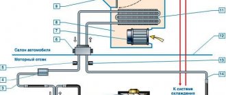
In the middle climate, the air entering the room must be heated. To do this, supply ventilation is installed with heating of the incoming air.
Heating of the coolant is carried out in various ways - with an electric heater, the intake of air masses near radiator or stove heating. According to SN and P, the temperature of the incoming air must be at least 18 degrees. Celsius.
Accordingly, the power of the air heater is calculated depending on the lowest (in a given region) street temperature. Formula for calculating the maximum heating temperature of a room with an air heater:
N/V x 2.98 where 2.98 is a constant.
Example: air flow – 180 cubic meters/hour. (garage). N = 2 kW.
Further 2000 W / 180 kb.m./h. x 2.98 = 33 deg.c.
Thus, the garage can be heated to 18 degrees. At outside temperature minus 15 degrees.
Heat load calculation
Calculation of the thermal load on ventilation is carried out according to the formula:
Q in = V n * k * p * C r ( t in – t nro),
in the formula for calculating the heat load for ventilation, Vn is the external volume of the building in cubic meters, k is the air exchange rate, tin is the average temperature in the building, in degrees Celsius, tnro is the outside air temperature used in heating calculations, in degrees Celsius, p is the air density , in kg cubic meter, Wed – heat capacity of air, in kJ cubic meter Celsius.
If the air temperature is below tnro , the air exchange rate decreases, and the heat consumption indicator is considered equal to Qв , a constant value.
If, when calculating the heat load for ventilation, it is impossible to reduce the air exchange rate, the heat consumption is calculated based on the heating temperature.
Heat consumption for ventilation
The specific annual heat consumption for ventilation is calculated as follows:
Q= * b * (1-E),
in the formula for calculating heat consumption for ventilation Qo is the total heat loss of the building during the heating season, Qb is domestic heat input, Qs is heat input from outside (sun), n is the coefficient of thermal inertia of walls and ceilings, E is the reduction factor. For individual heating systems 0.15 , for central heating systems 0.1 , b – heat loss coefficient:
- 1,11 – for tower buildings;
- 1,13 – for multi-section and multi-entry buildings;
- 1,07 – for buildings with warm attics and basements.
PRESSURE AND SECTION
The pressure and, accordingly, the speed of movement of air masses is affected by the cross-sectional area of the channels, as well as their configuration, the power of the electric fan and the number of transitions.
When calculating the diameter of the channels, the following values are empirically taken:
- For residential premises – 5.5 sq.cm. per 1 sq.m. area.
- For a garage and other industrial premises - 17.5 sq.cm. per 1 sq.m.
In this case, a flow speed of 2.4 – 4.2 m/sec is achieved.
Calculate the diameters of ventilation ducts
Further calculations are somewhat more complicated, so we will provide each step with examples of calculations. The result will be the diameter and height of the ventilation shafts of our one-story building.
We distributed the entire volume of exhaust air into 3 channels: 100 cubic meters. The hood in the kitchen is forcibly removed when the stove is turned on, the remaining 271 cubic meters goes through two identical shafts naturally. The flow rate through 1 air duct will be 271 / 2 = 135.5 m³/h. The cross-sectional area of the pipe is determined by the formula:
- F – cross-sectional area of the ventilation duct, m²;
- L – exhaust flow through the shaft, m³/h;
- ʋ—flow speed, m/s.
Reference. The air speed in the natural ventilation channels is in the range of 0.5–1.5 m/s. We take the average value as the calculated value - 1 m/s.
How to calculate the cross-section and diameter of one pipe in the example:
- We find the diameter size in square meters F = 135.5 / 3600 x 1 = 0.0378 m².
- From the school formula for the area of a circle, we determine the diameter of the duct D = 0.22 m. We select the nearest larger air duct from the standard range - Ø225 mm.
- If we are talking about a brick shaft embedded inside the wall, then the size of the ventilation duct 140 x 270 mm will fit the found cross-section (good coincidence, F = 0.0378 sq. m.).
Brick shafts have strictly fixed dimensions - 14 x 14 and 27 x 14 cm.
The diameter of the outlet pipe for a household hood is calculated in the same way, only the flow speed forced by the fan is assumed to be greater - 3 m/s. F = 100 / 3600 x 3 = 0.009 m² or Ø110 mm.
Degree of protection
Two main factors can pose a danger to ventilation units:
- hit by solid objects;
- exposure to water.
The international IP code (IngressProtectionRating) was introduced to indicate the degree of protection of devices from environmental influences due to design features.
Contains alphabetic and numeric symbols. It is indicated in the device passport and applied to the product body.
The first digit has a value from 1 to 6 and means protection against the ingress of solid particles and foreign objects
Table 1. Decoding of the first numeric value of the security code.
| Digital values | Decoding |
| 0 | Lack of any protection |
| 1 | Protects against penetration of objects larger than 50 mm |
| 2 | Protection against penetration of objects larger than 12 mm |
| 3 | Protection against penetration of objects larger than 2.5 mm |
| 4 | From debris larger than 1 mm |
| 5 | Partial protection against dust ingress |
| 6 | Complete dust protection |
Table 2. Decoding of the second digit of the code:
| Digital values | Decoding |
| 0 | No moisture protection |
| 1 | Vertical drop protection |
| 2 | From vertical drops falling at an angle no more than 15° from the vertical |
| 3 | From splashes, at an angle of no more than 60° from the vertical |
| 4 | Protects against drops and splashes from all angles |
| 5 | Jets hitting at any angle do not cause harm |
| 6 | Water entering the device does not interfere with the operation of the equipment |
| 7 | The device can operate when briefly immersed in water |
| 8 | Fully waterproof |
For example, the IP48 code means that the device is protected against the penetration of particles larger than 1 mm and can operate underwater.
The choice of device protection degree depends on the installation location and operating conditions of the fans.
Where and for what are industrial fans used?
From the name you can immediately guess that industrial fans are used mainly in production. They draw polluted air from the room, which often contains substances harmful and hazardous to health, and thereby provide a comfortable microclimate for all employees of the enterprise. As a result, all employees feel better and are more productive.
Industrial fans are also installed in warehouses and service establishments. The task is exactly the same: ensuring complete air exchange and creating a microclimate comfortable for work.
We recommend the product Industrial fan Systemair DKEX 250-4 Centrifugal (ATEX)
In stock
Air consumption, m³/hour: 2365 | Noise level, dB: 58.90 | Type: explosion-proof | Type: centrifugal | Diameter, mm: 250 |
Fan selection
Axial ceiling, wall and duct fans are able to clean sanitary rooms of any size from unpleasant odors and humidity. Before choosing a fan for bathroom ventilation, you need to know the parameters by which they need to be selected. So, let’s look at the example of popular models that meet all sanitary and hygienic requirements.
Fan model for a large ventilation duct
For example, overhead wall/ceiling fans Vents 100 Quiet. They are installed directly in the ventilation duct - the diameter of the devices is 100 and 125 mm. It is possible to install it in a flexible air duct using a clamp. Some models are fastened with screws, others do not have fastenings. The body is made of high-strength, waterproof plastic. The blades are aerodynamic. All components subject to vibration during operation are made of rubber, which reduces the noise level. The engine is on ball bearings. There is a timer - from 2 to 30 minutes. Productivity – 100 cubic meters/hour. The same parameters are available for axial fans, which can be mounted both in the wall and on the ceiling, MEROX W 100 BN and Electrolux E AF-100.
Axial duct fans are used for installation in an air duct. For a clear example, consider a ventilation fan for a private house or apartment Soler&Palan TD-Silent. It has a reduced noise level. To facilitate installation and maintenance, the device is equipped with mounting brackets. In addition, the presence of such devices allows you to mount it not only on a horizontal surface, but also on a wall. Quick release clamps have rubber seals. The terminal box rotates 360°. The Vents TT 100 duct fan has similar parameters.
The main parameter for choosing a fan is its performance. The required indicator is easy to calculate, knowing the area, ceiling height and air exchange rate of the room. Multiplying these values will give you the required fan power.
Features of centrifugal fans
Centrifugal fan
Units that are used to improve the operation of the ventilation system or involved in the air exchange process are divided into centrifugal and axial. Centrifugal fans for room ventilation are used in domestic, industrial, office and other buildings. The shape of their body is a snail, but despite this feature the design is quite simple. The housing has two openings: one sucks in air, the other releases it. In addition, there is a motor and blades. The mechanism of action of the fan is as follows: when turned on, the engine begins to rotate the blades, which suck in air and direct it directly into the housing under the influence of centrifugal force. Next, the air is directed into the air duct and, through a filter system, removed into the atmosphere.
Centrifugal fans are divided into:
- According to the pressure created (low - up to 1 kPa, medium - 1-3 kPa, high - 3-12 kPa).
- By purpose (general, special).
- In the direction of suction (one-way, two-way).
- According to the number of stages (single-stage, multi-stage).
Basically, centrifugal units are used for ventilation of industrial workshops or premises where high-capacity hoods are needed - office and shopping centers, public and educational institutions. In everyday life, they are used in private cottages to maintain the required microclimate in the bathroom, toilet, kitchen, and swimming pool.
Important! Since the fan housing is mainly made of metal, its use in wet rooms is limited. Therefore, when purchasing a device before installation, it is necessary to find out whether the housing or its constituent parts are subject to corrosion.
Application of axial (axial) fans
These devices differ from centrifugal ones not only in their operating principle, but also in their performance and size. They are more compact, unpretentious to the installation site (suitable for wet rooms), and do not require a special place for installation. Also, most models are easy to install and do not require special skills.
Axial fan
The device is a motor, during operation of which an axis rotates, with a screw mounted on it and an impeller. This unit is located in a housing having a circular cross-section. During operation, the air creates turbulence as it moves along the axis. The impeller is made of a fairly light material, so it does not create much resistance when it rotates.
Axial fans are divided into ceiling, wall, window, and duct fans. They are used to improve the quality of ventilation when natural exhaust is not enough. They have the following advantages:
- Compact sizes.
- Low noise level.
- Easy to install.
- The engine is protected from moisture.
- Wall-mounted models can be easily installed in the ventilation duct.
- Many models are equipped with a check valve (when the device is not working, they block the flow of air from outside).
- Low power consumption.