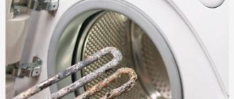
The thermal fuse, like a regular fuse, is designed to protect electronics from failure. The main difference from a conventional fuse is that it interrupts the supply circuit when the temperature rises. The temperature at which the protection operates is selected by the electronics manufacturer; accordingly, replacing a tripped thermal fuse is possible with the same one (with the same parameters). The parameters are written on the body. In addition to temperature, the current characteristic is important:
Thermal fuses come in two types: reusable (restored after tripping) and disposable (become completely inoperable after exceeding the temperature threshold).
It’s clear how to choose, but what to do if you go far or at night to get a new thermal fuse (shops are closed and the fan heater is out of order)? Is it possible to replace it with something temporarily or permanently? This question is asked by owners of multicookers, thermopots, water heaters, irons, microwave ovens, etc. technology.
“We turned it on, started doing something, and bang—it doesn’t work.” And we need it right now, urgently!
First of all, make sure that it was the thermal fuse that caused the device to turn off:
- Disconnect the device from the network.
- Make sure there is mains voltage.
- Check the regular fuse.
- Check the thermal fuse with a multimeter - set the multimeter to “continuity” or resistance measurement. A working fuse will show zero resistance, a blown fuse will show an open circuit.
On the left - intact (near zero resistance).
On the right is a burnt out one (open circuit). There are several replacement methods. But only one is true and reliable - replacing it with the same thermal fuse.
The given methods are “done by you at your own peril and risk.” The fuse doesn't just blow! Be extremely careful. Before replacing, inspect for possible short circuits or other damage or failure of the device.
Why did the iron burn out?
The most common cause of failure of the heating element is a rupture of the spiral. Another reason may be insufficient contact of the heating element rods with the device terminals at the connection points. On some models, the thermal fuse is included in one heater circuit, and the regulator is included in another.
Interesting materials:
How many m3 of boards per truck? How many Leroy stores are there in the world? How many stores does the tape have? What is the maximum foul in basketball? What is the maximum degree in beer? How much nicotine is the maximum in Snus? How much oil to add to carrot juice? How much oil to pour into Kia Sportage 3? How much oil is between the marks on the Kia Sportage 3 dipstick? How much oil do you need in puree?
Design and principle of operation of a multicooker
To successfully repair a multicooker with your own hands, you need to understand the device and the principle of its operation. The easiest way to understand this issue is to have a diagram of the multicooker device in front of your eyes.
In appearance, the multicooker resembles an ordinary saucepan, on the side of which there is a display and buttons for selecting the cooking mode. In its lower part there is a connector for connecting the network cable to the power supply and a switch. On top of the pan there is a hinged, hermetically sealed lid with a latch. If you press the button to open the lid, you will find a loose cooking bowl inside. The bowl resembles a saucepan without handles and is easy to remove.
The heating and operating mode control system of the multicooker is located in its lower part and is covered with a plastic lid, which is also the bottom of the multicooker. The heating system of a multicooker differs from the heating system of an electric kettle or iron only in the presence of a microprocessor control system for its operating mode.
Electrical circuit and device
The operating principle of multicookers of all models and manufacturers differs slightly, so after studying the design and operating principle of the REDMOND RMC-M23 multicooker, you will be able to successfully repair any other.
The 220 V supply voltage is supplied to the three-pin standard connector of the multicooker, located in its lower part. One of the connector pins is grounding, designated PE
, and
a yellow-green
wire is connected using a threaded connection to a metal housing.
The yellow-green
wire is also connected to the metal part of the multicooker lid.
Wiring diagram
Power supply to the multicooker is supplied using the wires indicated in the diagram L
and
N.
_ In the wire circuit L (red in the photo), a switch and a thermal fuse are installed in series. The switch is used to turn on, and the thermal fuse is used to protect against overheating.
From the thermal fuse, the supply voltage is supplied to one of the terminals of the heating element and the board of the Power and Switching Unit. Wire N (white in the photo) is connected to the Power and Switching Unit directly. The supply voltage from it to the second terminal of the heating element occurs when the contacts of the relay located on the board of the Power and Control Unit are closed.
Power supply and switching
One of the most loaded and often fails is the Power and Switching Unit. This block performs two tasks at once. Converts 220 V AC voltage supplied from the network into 5 V DC voltage (to power the control unit) and 12 V (to power the switching circuit), and provides, upon a signal from the Control Unit, the supply of 220 V supply voltage using a relay (black rectangular part ) on the heating element.
As you can see from the photo, some elements are missing on the board; it is obvious that the board is universal and only the elements necessary for the operation of the multicooker model REDMOND RMC-M23 were installed on it. Additional elements are installed if the board is used in other REDMOND models.
At the bottom left of the board you can see a metal disk covered in yellow insulation. This is a disk power supply (battery) of type CR2032 with a voltage of 3 V. The battery is designed to store cooking programs manually recorded by the cook in the memory chip of the multicooker control unit after disconnecting it from the network.
Control block
The brain of the multicooker is the Control Unit. Thanks to this unit, the multicooker, in comparison with the electric stove, began to meet all the modern requirements of kitchen masters.
The photo shows the control unit of the REDMOND RMC-M23 multicooker from the installation side of the elements. A dark square with pins on all four sides is the processor. On the other side of the board there are: a display, LEDs for menu illumination and operating mode control buttons.
The control unit is connected to the rest of the multicooker circuit using three connectors. Wires from the six-pin connector go to the Power and Switching Unit, and from two connectors with two contacts each go to two thermal resistors. White wires are connected to the thermal resistance, which is installed at the bottom of the pan, and blue wires are connected to the thermal resistance, which is located in the lid.
What task do thermal resistances perform in a multicooker?
Unlike constant resistances, thermal resistances (thermal resistors) greatly change their resistance when the ambient temperature changes. Thanks to this property, thermistors are widely used in household and industrial appliances as sensors for automatically adjusting and maintaining a given temperature.
The photo shows thermistors of type MF58 50 kOhm 1%, which are installed in the REDMOND RMC-M23. The MF58 thermistor is universal and is used to regulate temperature in many household appliances.
There are two thermistors installed in the multicooker, one is secured with adhesive aluminum tape on the metal part of the lid (pictured above), and the second is secured inside a spring-loaded glass at the bottom of the container (photo below).
After selecting the operating mode and pressing the “Start” button, the supply voltage is supplied to the heating element. After heating the lower thermal resistance (the bottom of the bowl in which the products are placed) to a certain temperature, the supply of voltage to the heating element is stopped until the temperature in the upper zone of the multicooker’s working capacity reaches a certain value. Then the heating turns on again and after a while turns off again. The frequency and duration of turning on the heating element depend on the selected mode and the volume of the bowl.
Thus, thanks to the presence of two thermistors, the microprocessor of the Control Unit constantly receives data on the heating temperature of the lower and upper zones of the bowl, which allows you to regulate the heating rate of products and maintain the required cooking temperature.
Why install a thermal fuse?
The thermal fuse is not directly involved in the operation of the multicooker and serves only to protect it from overheating in the event of a failure of the control system or a gross violation of the operating rules. If the temperature at the installation site of the thermal fuse reaches 170°C, it will trip and break the circuit. The multicooker will be de-energized and heating will stop. Blowing the thermal fuse is equivalent to turning off the switch.
Usually, in the electrical circuit of a multicooker of any model, a thermal fuse is installed, which you see in the photo. If it fails, the multicooker will have to be repaired. To do this, simply remove the bottom cover and replace the thermal fuse with a new one. But we must take into account that it is likely that the thermal fuse could have tripped due to a malfunction of the Control Unit or the Power and Switching Unit. Therefore, before replacing the thermal fuse, you must ensure that they are in good working order.
Attention! When repairing a multicooker and any other household electrical appliances connected to the household network, care should be taken. Touching exposed parts of a circuit connected to an electrical outlet may result in electric shock. Don't forget to unplug the multicooker from the socket! Just turning off the multicooker with the switch is not enough!
Small details make a big difference
Before purchasing, many people wonder why two seemingly identical multicookers can differ significantly in cost. The answer is simple: the difference in quality. It’s difficult to say how reliable thermal sensors are; it all depends on the assembly and adherence to technology in the manufacture of parts.
A temperature sensor is a small cylindrical product to which a wire or two is connected. Naturally, the thicker the wiring, the less likely it is that they will be interrupted.
Budget multicookers often suffer from thin and brittle wires, poor-quality assembly, when the wires are laid incorrectly, which causes fractures.
If we analyze the conclusions of service centers and various user reviews (both positive and negative), then such a breakdown usually occurs after a year of use. In devices of the lower price segment - earlier, but with premium multicookers this can only happen in the fifth year of use. A defective sensor fails within the first days or hours of operation.
Determining the cause
The principle of operation of the temperature sensor is quite simple: it measures the temperature and transmits the corresponding signal to the control board. Simply put, when the sensor heats up to a predetermined (programmed) temperature, it transmits a signal and the heating element turns off; when the temperature drops, it sends a signal again and the heating element heats up. Thus, the temperature regime is maintained. If the sensor breaks, then not a single program will work correctly, because it will not give the appropriate command to the heating element.
It is important to know! Incorrect operation of the sensor does not always indicate that it is grinding; perhaps there is not enough contact or there is no thermal paste.
Most often, the top sensor breaks down. The wires from it go to the bottom of the multicooker, where the main mechanism is located. During use, the cover constantly opens and closes, which can lead to broken wires.
When the temperature sensor of a multicooker does not work correctly or fails, the following happens:
- The device does not turn on and does not show any “signs of life”.
- An error flashes on the display, informing about water getting inside/temperature sensor failure/short circuit; it is often marked E1 (E0, E2, E3, E4), but different manufacturers may have their own code.
- The multicooker works, but no program starts.
- The device starts the program but turns off prematurely.
The lower sensor controls the temperature of the bowl itself, which is heated by a heating element or under the influence of a magnetic field in induction multicookers. If the container does not fit tightly to the heating element (not the original one), then the sensor receives incorrect temperature data, which can lead to overheating of the entire device or incorrect operation.
How to repair a multicooker with your own hands
Having studied the structure and operating principle of the multicooker, it will not be at all difficult to repair it with your own hands. Often, for repairs, all you need is a screwdriver, but if you’re unlucky, then also a multimeter and an electric soldering iron.
Decoding error codes for the REDMOND multicooker
If the multicooker does not work, then in case of some malfunctions, an error code may appear on the display, indicating which element or unit is supposedly faulty.
| REDMOND multicooker error code table | ||
| Error code | Which element or node failed | Note |
| E1 or E2 | System error. Possible failure of the power supply and switching unit, heating element or the lid is not tightly closed | The REDMOND RMC-M23 multicooker does not have control over the position of the lid |
| E3, E4 or E5 | Failure of the temperature sensor (thermal resistance) or the overheating protection system has tripped | The REDMOND RMC-M23 multicooker has a thermal fuse, and if it is blown, the display will not light up |
As you can see, self-diagnosis in multicookers is not very informative, and error codes do not provide any useful information for repair, but only inform that the multicooker needs to be repaired.
The multicooker does not work, the display does not light up
If the multicooker does not work, and the display does not even light up, then the first thing you need to do is make sure that there is supply voltage in the outlet to which the power cord is connected. To do this, just connect any household appliance, such as a table lamp, to it.
The multicooker is a stationary household appliance and therefore the power cord cannot fray during its operation. But if pets live in the apartment, then it is quite possible that the cord could be damaged by their teeth. Therefore, it is necessary to visually inspect the cord for damage and at the same time check whether it is well inserted into the multicooker connector.
If the above steps do not lead to success, then you need to unplug the cord from the socket and remove the bottom cover of the multicooker by unscrewing one screw. The lid is additionally secured with several latches, but they are small and the lid is easily separated from the body.
After removing the cover, you must carefully inspect the places where the wires are connected to the network connector and the terminals of the heating element. The wires must fit tightly to the contacting surfaces of the terminals and no blackening or carbon deposits should be visible.
If loose contacts are found, then the screws need to be tightened, and if they are burnt, then clean the contacts using fine sandpaper. After this, you need to check the functionality of the multicooker.
Checking the switch, thermal fuse and heating element
If the inspection did not reveal the malfunction, then it is necessary to check the switch and thermal fuse, which are connected to each other by a thick red wire. To do this, you need to use a multimeter or pointer tester, in resistance measurement mode, to touch points 1 and 2 with the probes; the resistance should be zero. At the same time, you need to ring the heating element, measuring the resistance between points 1 and 3 (or 2 and 3). It should be equal to the resistance of the heating element spiral, and, depending on its power, be 30-80 Ohms.
If the resistance between points 1 and 2 approaches infinity, then the switch or thermal fuse is faulty. To check the switch, you need to set its key to the “on” position and touch its exposed terminals with the probes of the device. The resistance should be zero. If the switch is working properly, then the thermal fuse is checked next.
To check the thermal fuse, you need to release the rack that attaches it to the multicooker body and move the insulating tube. Next, touch the multimeter probes to its terminals. The resistance should be zero. Otherwise, the thermal fuse has failed and must be replaced. The method of replacing the thermal fuse is discussed in the article “Do-it-yourself heater repair.” The thermal fuse has no polarity, so it can be installed as convenient.
How to check the switch and thermal fuse without instruments
You can check the serviceability of the switch and fuse without a measuring device. To do this, just connect points 1 and 2 with a piece of wire with a cross-section of at least 1 mm2. After that, replace the lid and connect the multicooker to the network. If it works, it means the thermal fuse has failed. It is unacceptable to operate a multicooker with a shorted thermal fuse, except as a last resort, and under the obligatory condition that a person is near it.
Checking the Control Unit
The display may not glow if the CU board is not supplied with a 5 V DC supply voltage from the BOD or the microprocessor has failed. The presence of voltage can be checked using a multimeter. If the voltage is normal, then it is necessary to remove the board from the multicooker and carefully inspect for blackening or destruction of elements, the integrity of printed conductors and the quality of soldering.
To remove the control board from the multicooker body, you need to unscrew two screws, as shown in the photo.
Next, remove the upper part of the control unit from the multicooker body and move it up. To access the printed circuit board, you will also need to remove the plastic cover, which is held in place by four self-tapping screws.
If the CU board does not receive a 5 V supply voltage, then the fault should be looked for in the BOD. If the supply voltage is supplied to the control unit board and an external inspection does not reveal any defects, then the microprocessor has failed and you will have to purchase a new control unit for repair. The microprocessor installed in the multicooker control unit is programmed for the algorithm of its operation, and simply replacing it will not help to repair the multicooker.
Malfunctions may still occur in the control board that do not affect its performance, but reduce the comfort of use. This is poor operation of the buttons, lack of display numbers or indication of the turned on cooking mode. Such malfunctions are eliminated by replacing the failed element.
The multicooker does not work, the display lights up
If one of the E-error codes is displayed on the control panel display, then the power cord, switch and thermal fuse are in order. Thermal resistances, heating elements or power and switching units may be faulty.
How to check thermal resistance
Thermal resistances in the multicooker are connected directly to the Control Unit using two separate connectors. A white connector with blue wires coming from it is connected to a thermistor, which is located in the lid of the multicooker. And using a black connector with white wires, a thermistor installed in the bottom glass of the multicooker is connected.
Before checking the thermal resistances, it is necessary to disconnect the connectors from the Control Unit. To measure thermal resistances you will need a multimeter or pointer device.
Next, use the multimeter probes to touch the contacts of one and then the other connector and measure the resistance value. The polarity of connecting the multimeter probes does not matter. If you place your palm on the place where the thermal resistance is installed during measurement, its value will increase.
The REDMOND RMC-M23 multicooker is equipped with thermal resistances of the same size, type MF58 with a nominal value of 50 kOhm. In multicookers of other models, the rating may be different. Thermal resistance is operational if its value is not zero or infinity.
How to check the heating element
Heating elements in household electrical appliances are usually the last to fail. A separate article “How to check and ring a tubular electric heater heating element” is devoted to the device and methods for checking the heating element.
The photo shows the findings of the heating element. The resistance of the spiral of a working heating element of the REDMOND RMC-M23 multicooker should be about 80 Ohms.
How to check the Power and Switching Unit
If in the previous steps the cause of the multicooker malfunction was not discovered, then you need to check the Power and Switching Unit (BPK). This unit operates in severe temperature conditions and may fail first.
In the REDMOND RMC-M23 multicooker, the +5 V voltage that powers the Control Unit (CU) and +12 V to power the switching circuit are obtained from the 220 V mains voltage using two separate circuits. Therefore, in the multicooker that had to be repaired, the part of the BOD circuit that generates the +5 V voltage worked, so the control unit worked and displayed error code E1 on the display. There was no +12 V voltage.
Upon careful inspection of the parts of the BOD, the attention was drawn to the resistor-fuse R100, the gray color of which was uneven. The multimeter showed that its resistance was infinity, although according to the color marking it should be 100 ohms.
To repair the BOD board, it must be removed. The board is attached to the base of the multicooker using two screws with metric threads and nuts, which must be held when unscrewing the screws. It is possible to get to the nuts only from the installation side of the cooking bowl by removing the heating element, which is secured with three screws. It is not necessary to disconnect the wires from the heating element terminals.
When the resistor was removed from the circuit board, it became obvious that it had burned out. This is clearly visible in the photograph. The resistor in the circuit functions not only as a current limiter, but also as a fuse. Consequently, its destruction was caused by the large current flowing through it, which could only flow in the event of a short circuit in the elements connected after this resistor.
To make it easy to find the malfunction of the multicooker, I drew part of the electrical circuit diagram of the BOD, which is responsible for generating a voltage of +12 V. Checking the resistance between the terminals of capacitor C3 showed the presence of a short circuit. Capacitor C3 and resistor R1 were soldered off, but the short circuit did not disappear. It became obvious that the PN8024R chip was faulty.
To be completely sure, I found a typical connection diagram for the PN8024R microcircuit, which you see above. Since a short circuit occurred between the SW and GND terminals, it became obvious that a breakdown had occurred between the drain and source of the field-effect transistor inside the microcircuit and to restore the operation of the multicooker, it must be replaced.
Upon closer inspection of the microcircuit body, small local darkening was discovered on the side with markings, which are clearly visible in the photograph.
How to replace a standard +12 V source with an external power supply
The PN8024R chip turned out to be rarely used in household appliances, and it could only be obtained several weeks after ordering it online. There were several adapters available from different computer devices, and the idea arose to select a suitable adapter for +12 V voltage and replace the non-working part of the BOD circuit with it.
The choice fell on the adapter, on the body of which it was stated that it produces a constant voltage of +12 V and is designed for a load current of up to 200 mA, which fully corresponded to the parameters of the PN8024R microcircuit. However, when testing this adapter at a 60 Ohm load, it turned out that the output voltage is 17 V. Obviously, the unit produces an unstabilized voltage, which is stabilized in the device to which the unit is connected. Such a block was clearly not suitable for the output voltage.
There was no longer an adapter with an output voltage of 12 V, but one with an output voltage of 9 V. Taking into account the fact that it was necessary to power a circuit consisting of only two transistors and a relay, I decided to check whether it would work on nine volts. After all, electromechanical type relays usually operate when a much lower voltage is applied to the winding than according to the passport. Testing the adapter under and without load showed that the output voltage does not change and is equal to 9 V.
Before connecting the adapter to the BOD, you must disable the standard stabilizer. To do this, you need to unsolder resistor R100 and diode D106, as in the photo.
There was no 100% certainty that the 9 V adapter would work. In order not to open the adapter case or cut its output cord during testing, the adapter was connected to the multicooker BOD via a standard connector. The plus is located on the central pin of the connector.
The terminals from the connector were soldered, observing polarity, parallel to the terminals of capacitor C105 of the BOD board. The bottom cover was installed in place, the multicooker was connected to the network and then the adapter was plugged into the network. The multicooker started working. To check the reliability of its operation, water was poured into the cooking bowl to the brim, and in the “Cooking” mode of the multicooker, the water was brought to a boil and boiled for 45 minutes until the timer went off. Tests confirmed the correctness of the chosen solution.
All that remains is to install the adapter in the multicooker and connect it to the BOD. To do this, the contact pads of the adapter board, to which it is necessary to supply a supply voltage of 220 V, were connected using wires to the terminals of the BOD board, as in the photograph (yellow and red wires). The +9 V supply voltage was supplied using a pair of red and black wires.
For better thermal operation of the adapter, the part of the case on which the power plug was located was not installed. The photo shows the view of the multicooker, with the bottom lid raised and the adapter attached to it.
Before attaching the adapter to the lid, a place was chosen that would prevent it from resting on the multicooker part after closing the lid. A hole was drilled in the lid so that the threaded part of the self-tapping screw would pass freely, and in the adapter body so that it could be screwed in. The photo shows the head of the screw that secures the adapter to the multicooker.
The multicooker does not remember manually set cooking modes
After many years of use, the REDMOND RMC-M23 multicooker may, after disconnecting it from the network, stop saving manually selected cooking programs in the “multi-cook” mode. This is usually due to the battery being discharged.
The battery is usually installed in the Power and Switching Unit. The appearance of the battery is shown in the photograph. Similar 3V CR2032 batteries are widely used in consumer electronics. To check a battery, you need to measure the voltage at its terminals. It should not be less than 3 V, otherwise the battery must be replaced.
Repairing the multicooker lid hinge
In the multicooker that had to be repaired, in addition, the hinge holding the lid was broken. It was possible to cook food, but there was no seal, and if handled carelessly, the wires connecting the thermal resistance installed in the lid to the control board could easily be torn.
The multicooker lid consists of two halves, which had to be separated to repair the hinges. The lid halves are fastened together using several latches.
The latches are small and therefore the lid can be easily separated using a flat-head screwdriver squeezed between its halves. The photo shows one of the latches.
In order to get to the mating part of the loop, you need to remove the steam condensate collector and unscrew one screw. It turned out that the yellow-green wire grounding the lid was broken.
Both cover hinge pin holders were seriously broken. Yes, this is not surprising, since the part of the cover that holds the hinge axis was plastic and only a couple of millimeters thick. The mistake of the multicooker developers is obvious.
A steel paper clip was used to repair the hinge eye. One end of it was first straightened and then bent at an angle and cut with side cutters along the yellow line, as in the photograph. Next, the corners of the paperclip were fused into the base of the lid. This work requires patience. It is necessary to hold the part made from a paper clip with tweezers and heat it by applying a soldering iron tip to it until it is sunk into the plastic base of the lid to the required depth.
In the photo you see the result of repairing the multicooker lid hinge. The appearance is not very beautiful, but the loop will be covered by the second half of the lid and will not be visible from the outside. But the restored loop turned out to be much stronger than the previous one.
Why does food stick to the walls of the multicooker bowl?
Many multicooker users eventually encounter the problem of food sticking to the walls of the bowl. In this case, solid products, regardless of the amount of oil poured, begin to stick to both the walls of the bowl, coated with Teflon (fluoroplastic) and with a ceramic coating.
There can be two reasons for sticking - a violation of the temperature regime of the multicooker or wear on the coating of the bowl. The answer is simple. If stuck food also burns, then the temperature regime is to blame, and if it sticks without burning, then the coating of the bowl has worn out.
All attempts to restore the quality of the coating using vinegar, table salt or other methods can only give a temporary effect. If the coating of the pan is worn out, then only buying a new bowl will help prevent it from sticking.
If the Teflon film in the bowl is very thin, it is easily scratched to the base even with minor mechanical impact. When stirring food, the sharp edge of a wooden spatula always slightly scratches the coating, and over time, a combination of microscopic scratches, which are difficult to notice with the eye, lead to food sticking. The Teflon coating is sensitive to high temperatures and when heated above 270°C it is destroyed, and as a result, food also begins to stick.
In order for kitchen utensils coated with Teflon to serve for a long time, the thickness of the film must be significant. Teflon is expensive and therefore high-quality kitchen utensils with Teflon coating cannot be cheap.
All of the above also applies to ceramic-coated cookware. After all, this type of coating has nothing in common with ceramic tableware and is a nanocomposite polymer, which contains about 5% sand nanoparticles. Currently, the service life of dishes with a ceramic coating is many times lower than with Teflon.
Therefore, it is better to buy Teflon-coated cookware from well-known manufacturers who will not skimp on the thickness of the Teflon coating.
Mulinex multicooker - what kind of breakdowns are indicated by codes e0-e5
The most detailed information about faults and their codes on the control panel is provided by Mulinex: problems with each resistor or board has its own unique identifier.
Error E0 on the control panel of the Mulinex multicooker means that the temperature sensor at the top of the device is closed or open
The most frequently occurring codes are collected in the table.
| E0 | Upper sensor shorted or open |
| E1 | Open or short circuit of the lower temperature sensor |
| E2 | Malfunction of the power board |
| E3 | Control board is not functioning |
| E4 | Temperature sensor short circuit |
| E5 | Thermistor break |
Methods for replacing the thermal fuse
Diagnostics confirmed that the fuse was blown - this is a good reason to take care of the condition of the circuit in which it is located. Most likely she is finished.
For example, there is no alternative to replacing a disposable thermal fuse. You can only temporarily close the circuit in a reliable way:
If you cannot perform this procedure at home, it is better to contact a specialist, this will be more reliable and the equipment will last longer.
Such methods leave the device unprotected, and with the next temperature jump the system will fail. The thermal fuse is broken, it is better to throw it away and replace it with a new one. It's not expensive.
Privacy Overview
Necessary cookies are absolutely essential for the website to function properly. These cookies ensure basic functionalities and security features of the website, anonymously.
| Cookie | Duration | Description |
| cookielawinfo-checkbox-analytics | 11 months | This cookie is set by GDPR Cookie Consent plugin. The cookie is used to store the user consent for the cookies in the category “Analytics”. |
| cookielawinfo-checkbox-functional | 11 months | The cookie is set by GDPR cookie consent to record the user consent for the cookies in the category “Functional”. |
| cookielawinfo-checbox-others | 11 months | This cookie is set by GDPR Cookie Consent plugin. The cookie is used to store the user consent for the cookies in the category “Other. |
| cookielawinfo-checkbox-necessary | 11 months | This cookie is set by GDPR Cookie Consent plugin. The cookies are used to store the user consent for the cookies in the category “Necessary”. |
| cookielawinfo-checkbox-performance | 11 months | This cookie is set by GDPR Cookie Consent plugin. The cookie is used to store the user consent for the cookies in the category “Performance”. |
| viewed_cookie_policy | 11 months | The cookie is set by the GDPR Cookie Consent plugin and is used to store whether or not user has consented to the use of cookies. It does not store any personal data. |
Advertisement cookies are used to provide visitors with relevant ads and marketing campaigns. These cookies track visitors across websites and collect information to provide customized ads.
Analytical cookies are used to understand how visitors interact with the website. These cookies help provide information on metrics the number of visitors, bounce rate, traffic source, etc.
Functional cookies help to perform certain functionalities like sharing the content of the website on social media platforms, collect feedback, and other third-party features.
Other uncategorized cookies are those that are being analyzed and have not been classified into a category as yet.
Performance cookies are used to understand and analyze the key performance indexes of the website which helps in delivering a better user experience for the visitors.
Source
Fuses in Redmond
Why are thermal fuses needed? The reader will immediately interrupt - protect the overheated device. We see reasons to say: thermal fuses are needed to repair Redmond multicookers more often.
How disparate facts are connected. This is what the owner, an experienced multicooker user, writes to members of the forum: “Accidentally turned on the device without a pot, noticed after 40 seconds, immediately turned off the device.” The woman wanted to know what would happen to the Redmond M90 if she didn’t put the pot back in place at all.
Dobrokhot suggested: nothing terrible will happen. The main button (see above), located under the bottom of the pot, will prevent the multicooker from turning on in the absence of dishes. The hostess conducted an experiment: with the lid open (!) and the pot pulled out, she launched the program. Within 10 seconds the heating element became hot. The result is stunning: there is no protection against incorrect switching on in the Redmond multicooker.
What will happen if you leave the cook unattended as a kitchen assistant for a long period of time. The conclusion is suggested by an advanced forum member: to protect against overheating, there are thermal fuses inside. Security elements cope with their function only once - when they burn out. After an incident, the intervention of a “specialist” will be required.
Actually, for this purpose we are considering the manual repair of Redmond multicookers - when the reason is known, the repair becomes a simple matter. If a multicooker once left unattended refuses to turn on, the problem is probably the thermal fuses.
Now let’s read the service book issued to the buyer of the Redmond multicooker. Quotes are selective so as not to bore the reader with too much information. Warranty repairs are not carried out if “the product has... thermal or other damage caused by improper operation...”.
Redmond multicooker, warranty repair - are the two things compatible? Not if you have developed a habit of leaving the device on unattended! The main button under the pot is present to measure the temperature and maintain the correct cooking modes.
In this regard, I would like to remember users who, having forgotten to install the pot, pour liquid inside and pour out cereals. Be extremely careful. If something irreparable happens, immediately unplug the cord from the 230 V socket. The device must be cleaned. The following information was found: it is possible to simply rinse with water, dry the microcircuits for 1 week at room temperature... Naturally, you can use the method at your own peril and risk. The official instruction manual does not provide for anything like this.
Other renovation examples
However, repairs require certain knowledge, skills and, finally, spare parts.
The manufacturer may well fill the terminals with a compound (by the way, this speaks rather in his favor); the fuses used, depending on the power of the multicooker, are also different. We found many interesting repair cases when you have to disassemble the multicooker and clean the heating element, for example, from jam. But the following video amazed us with the ingenuity of the Russian master in finding an unexpected replacement for the power supply of the electronic filling of the device. So, if you are not yet tired of this topic, please come to our cinema hall.
Correct operation
It is very important to use the multicooker in full compliance with the recommendations specified in the manufacturer's instructions. Particular attention should be paid to the sequence of placing products in the miracle saucepan:
- We take out the bowl.
- We put in the ingredients intended for the dish.
- Place the bowl in the multicooker.
This sequence cannot be broken. If you simply put food in a saucepan installed in a multicooker, liquid may get inside the device. Then you can get the problem again that the multicooker stops turning on.
Performance test:
I set the multimeter to continuity. old fuse:
new:
heat the new fuse:
new after heating:
works.
Causes of error E4
A multicooker, like any equipment, can fail. One of the most common errors is E4, which indicates that the pressure sensor is clogged. In some cases, the breakdown is due to problems in the electronic board. Improper operation of the multicooker leads to this common mistake.
How to fix the problem?
To troubleshoot the problem, you may need the most popular option: a screwdriver for unscrewing bolts, an understanding of Ohm's law, and a temperature sensor (100 ohm or 50 ohm). Cleaning it from oxide may be sufficient. You can buy a temperature sensor at any radio store; it is better to change it. Reflashing, wiping with a cloth and other manipulations usually do not help. Below we have provided answers to almost all error codes; use them to determine what is faulty in the multicooker. After this, the faulty element will need to be replaced or soldered.
Umedia Service provides post-warranty repairs of multicookers with free diagnostics in 21 service centers in St. Petersburg and at home! For repairs, only original spare parts from the manufacturer are used.
Causes of errors E1, E2, E3
An error in the E1 multicooker indicates moisture ingress or overheating of the heating element. If there is a short circuit in the heat sensor located on the cover of the device, error E2 appears on the display. On some device models, the error indicates a broken connecting wire. To accurately determine the error, you should check the equipment components with a multimeter. If error E3 appears, dry the inside of the device and check that the lid is tightly closed. If the multicooker does not turn on, you will not be able to display the error on the display.
What is a thermal fuse
The thermal fuse is an electromechanical thermal switch with a fixed response temperature. It is used to protect the device from overheating, overcurrent of windings of single and three-phase AC and DC electric motors.
It is used in household appliances and the automotive industry. Thermal fuse is found in microwaves, lawn mowers, dryers, washing machines and other appliances.
Aupo bf121 what can be replaced
New Books Spy Things: New and Best Circuits for Ham Radio: Spy Things and More 2nd Edition Arduino for Inventors. Electronics training using 10 entertaining projects: We design robots. A guide for beginners Computer in a radio amateur laboratory Radio designer 3 and 4 Spy stuff and protection against them. Collection of 19 books Entertaining electronics and electrical engineering for beginners and not only Arduino for beginners: the simplest step-by-step tutorial Radio designer 1 Updates High-power cellular jammer.
Search data for your request:
Wait for the search to complete in all databases. Upon completion, a link will appear to access the found materials.
Go to search results >>>
WATCH THE VIDEO ON THE TOPIC: What to do if the iron stops heating. Replacing the thermal fuse
Fuse in a domestic heater
The thermal fuse of the RY series is designed for operating current - 10A, operating voltage V. The RY thermal fuse is also designed for protection against current overload.
If one of the specified parameters exceeds the rated temperature of the fuse, the operating current opens and de-energizes the circuit, thereby preventing fire. Since the RY fuse is not recoverable, it must be replaced after it blows. With this method, replacing the RY thermal fuse is greatly simplified due to the fact that the thermal fuse terminals are located on the axial sides. I placed an order and paid using a PB card.
Initially, the SMS for payment never arrived, but then a day later they called back and asked why there was no payment, he said that the SMS did not arrive. As a result, an SMS was sent immediately, I made payment and the goods were delivered the next day by new mail. Thanks for your feedback.
We are moving to a new site, so sometimes there may be glitches. We apologize. Current - 10A, voltage - V. Thermal fuse dimensions are 4x11 mm. We moved! Our new address: st. Khmelnitskaya, Rating star star star star star. Leave your review about the product. Subscribe to our newsletter. Subscription completed. Your cart There are now items in your cart:. Continue shopping Place your order. Total: UAH.
How to check the thermal fuse?
Where to buy in St. Petersburg: Vyborskaya embankment, Smolenskaya village, building V, office. VSKH brand meters are used to measure the volume of water passing through the supply pipeline of a cold water supply system with a passage opening diameter of 15 mm.
Thermal fuse AUPO P2-3A-F in a blender
FOOD SERVICE EQUIPMENT
Samsung thermal fuse, how to install it correctly A colleague gave these thermal fuses for Samsung refrigerators for free. They are very Element of the circuit in the blender Good day. Help me identify a blender circuit element.
2015/2016 FOOD SERVICE EQUIPMENT
Thermal fuse 250V 10A 121 + performance test + replacement
DIY fan heater repair
Request warehouses. Question about replacement. Go to new.
Car t20 7443 white 13 smd led light bulb lamp side turn signal brake tail
VIDEO ON THE TOPIC: Soldering thermal fuses (replacement)
Support 4 channels automatically adapt to 2ch, 3ch and 4ch modes 2. High-performance processor improves control precision 3. This model mat will perfectly fit your car trunk. Such a car mat is guaranteed to protect the trunk from dirt, debris and dust that constantly accumulate in this compartment. And besides, the tray does not allow moisture to pass through.
I have not found either originals or similar forms of metal thermal fuses for sale in our city. Accordingly, the question. Can I replace the original with a similar product? Or what can you advise on the topic? We accept Sprint-Layout 6 format! Export to Gerber from Sprint-Layout 6.
The company Zumex, Maquinas y Elementos S. A, founded in 2009, is developing a completely new, unique range of automatic juicers for trade, hotel and restaurant businesses. Accessories for juicers.